Precision Obstacle Avoidance: Building a Dual-Ultrasonic SPI System with ATmega32 and Raspberry Pi. In modern robotics, reliable obstacle detection is the difference between a project that works and one that crashes. While the Raspberry Pi is a powerhouse for AI and logic, its Linux kernel isn’t designed for the microsecond-level timing required for ultrasonic sensors.
The solution? A hybrid architecture that pairs the real-time reliability of an ATmega32 with the high-level processing power of a Raspberry Pi.
In this guide, we’ll build a dual-sensor SPI-based distance measurement system that eliminates sensor crosstalk and provides jitter-free data.
The Hybrid Architecture
To achieve professional-grade performance, we split the system into two distinct roles:
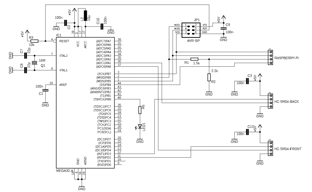
- The Reflex System (ATmega32): Acting as the slave controller, the ATmega32 manages ultrasonic pulses. Because it handles the hardware interrupts directly, it eliminates the “latency jitter” common in multitasking Linux environments.
- The Brain (Raspberry Pi): The Pi acts as the master node, orchestrating the system and requesting data via the SPI (Serial Peripheral Interface) bus.
Why SPI?
Unlike I2C, which is multi-master capable and prone to bus contention, SPI is a high-speed, synchronous protocol perfect for point-to-point communication between our microcontroller and the Pi.
The Physics of Ultrasonic Distance
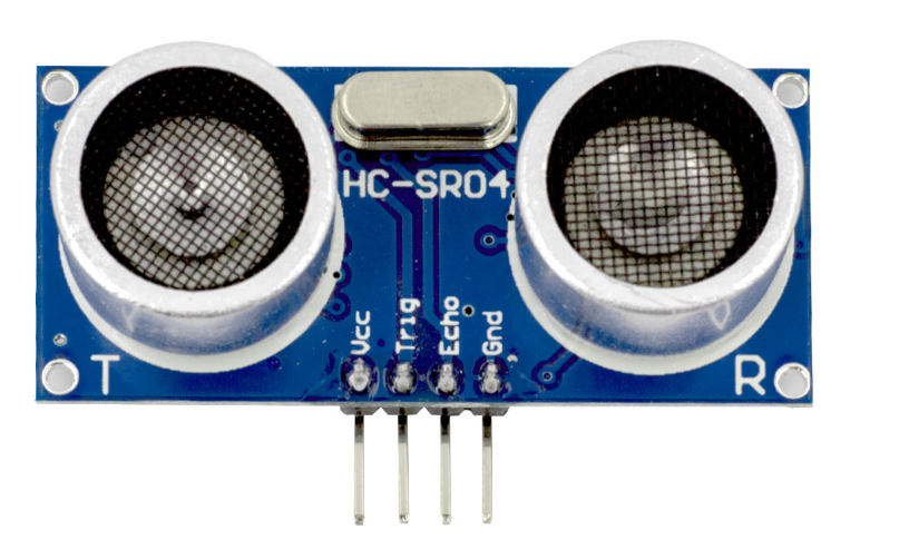
The HC-SR04 sensor uses the Time-of-Flight (ToF) principle.
It emits a 40 kHz burst by a voltage pulse length of min 10µs on pin “Trig” and measures the pulse time () on pin “Echo” it takes for the echo to return.
The formula:
d_{distance} = \frac{1}{2}\; v_{ultrasonic}\;t_{pulse}=\frac{1}{2}\; 343\frac{m}{s}\;t_{pulse}- : Distance to object
- : Speed of sound (~343 m/s at 20°C)
- : Time duration of the pulse
Implementation Strategy
We implemented the distance measurement in C language on an ATmega32 microcontroller without using an operating system. The Timer Unit has been set up to create a millisecond tick count.
Crosstalk Mitigation
Firing two sensors simultaneously often results in “ghosting” – where one sensor detects the reflection of another. We use a non-blocking state machine to ping the front and back sensors alternately every 32ms.
void Distance_Process( void )
{
   ...
   // Get actual timer tick count (1digit = 1ms)
   ulTick = Timer_Tick();
   // Timer (32ms) expired
   if( ulTick > ulTickTimeout )
   {
      // Alternate sensor trigger
      if( byDistSensor == 0 )
      {
         DIST_TRIG_BACK_OFF();
         DIST_TRIG_FRNT_ON();
         byDistSensor = 1;
      }
      else
      {
         DIST_TRIG_FRNT_OFF();
         DIST_TRIG_BACK_ON();
         byDistSensor = 0;
      }
      // Load next 32ms timeout
      ulTickTimeout = ulTick+(uint32_t)32;
   }
   ...
} For the timer tick count an “unsigned long” data type (32Bit) is used without an overflow handling. Reason is that for most applications a counter overflow will not occur within life cycle.
Distance Calculation
The digital input pin of the sensor echo is read in polling mode. After toggling to high level the timer counter is read as pulse start and then waiting until the echo has been received as a pulse end.
void Distance_Process( void )
{
   ...
   if( byDistSensor == 0 )
   {
      // Sensor 1 active
      byDistSens = DIST_SENS_BACK();
      if( (byDistSens != 0) && (byBackPinOld == 0) )
      {
         byBackPinOld = byDistSens;
         uiDistPulseStart = TCNT1;
      }
      else
      if( (byDistSens == 0) && (byBackPinOld != 0) )
      {
         byBackPinOld = byDistSens;
         uiDistPulseEnd = TCNT1;
         if( uiDistPulseEnd < uiDistPulseStart )
         {
            byDistBackPulse = (byte)((((uint16_t)0xFFFF - uiDistPulseStart) + uiDistPulseEnd) >> 6);
         }
         else
         {
            byDistBackPulse = (byte)(((uint16_t)(uiDistPulseEnd - uiDistPulseStart)) >> 6);
         }
      }
   }
   else
   {
      ...
   }
   ...
}The echo or pulse duration is calculated considering timer overflow. Without overflow happened, it is a simple calculation based on pulse end minus pulse start, where 1 digit represents 1 millisecond.
To fit into 8 Bit the calculated echo or pulse duration is divided by 64 (shift operation by 6 Bits).
SPI Communication
The system remains responsive by avoiding blocking functions, ensuring the SPI buffer is always ready for the Raspberry Pi. The ATmega32 remains an SPI slave, waiting for the Pi to request specific sensor data.
void Control_Process( void )
{
   ...
   if( (SPSR & 0x80) != 0 )
   {
      // SPIF in SPSR cleared after reading SPDR
      byIndex = SPDR;
      // Load SPI data register to send for next cycle
      if( byIndex == (byte)0 )
      {
         SPDR = Distance_Front();
      }
      else
      if( byIndex == (byte)1 )
      {
         SPDR = Distance_Back();
      }
      ...
   }
   ...
} Our implementation uses the ATmega32’s 16-bit Timer1 to capture pulse widths with microsecond precision, normalizing the result into a byte for efficient SPI transmission.
Crucial Hardware Considerations
- Logic Level Shifting: The ATmega32 runs at 5V, while the Raspberry Pi GPIOs are strictly 3.3V. Always use a 4-channel bi-directional logic level shifter. Skipping this will almost certainly fry your Pi’s GPIO pins.
- Common Ground: Ensure the GND pins of the ATmega32, the HC-SR04 sensors, and the Raspberry Pi are connected. Without a common ground reference, your SPI data will be corrupted by electrical noise.
Conclusion
By offloading timing-critical tasks to the ATmega32, we create a robust, modular sensor array that keeps your Raspberry Pi free to run high-level autonomy logic. This “Master/Slave” design is the standard for reliable robotics.
Ready to start? Start by verifying your SPI bus communication with a simple loopback test before connecting the ultrasonic sensors. Happy coding!
Find source code for ATmega32 used in this blog written in C and the SPI master code for Raspberry Pi written in C++ on GitHub.